The Unified Modeling Language or UML is not a textual language, but a set of
graphical notation techniques to “specify, visualize, modify, construct, and
document the artifacts of an object-oriented software-intensive system under
development.” UML evolved from 1995 to the present through the unification of
previously-distinct modeling language standards and diagram types, which Figure
11.5 lists.
While this book focuses on more lightweight Agile modeling—indeed, UML-based modeling
has been criticized as being too “bloated” and heavyweight—some types of UML diagrams
are widely used even in Agile modeling. Figure 11.6 shows a UML class diagram, which
depicts each actual class in the app, its most important class and instance variables
and methods, and its relationship to other classes, such as has-many or belongs-to
associations. Each end of the line connecting two associated classes is annotated with
the minimum and maximum number of instances that can participate in that “side” of the
association, called the association’s multiplicity, using the symbol * for “unlimited”.
For example, a multiplicity 1..* means “one or more”, 0..* means “zero or more”, and 1
means “exactly one.” UML distinguishes two kinds of “owning” (has-one or has-many) associations.
In an aggregation, the owned objects survive destruction of the owning object. For example,
Course has many Students is an aggregation because the students happily don’t get destroyed
when the course is over! In a composition, the owned objects are usually destroyed when the
owning object is destroyed. For example, Movie has many Reviews is a composition since
deleting a Movie should cause all of its reviews to be deleted.
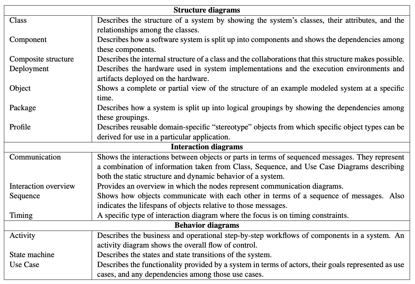
Figure 11.5: The fourteen types of diagrams defined by UML 2.2 for describing a software system. These descriptions are
based on the excellent Wikipedia summary of UML5
, which also shows an example of each diagram type. Use case diagrams
are similar to Agile user stories, but lack the level of detail that allows tools like Cucumber to bridge the gap between user
stories and integration/acceptance tests.
Figure 11.6: This UML class diagram shows a subset of the classes in the theater-ticketing app consistent with Figures 9.4
and 9.5. Each box represents a class with its most important methods and attributes (responsibilities). Inheritance is
represented by an arrow. Classes with associations are connected by lines whose endpoints are annotated with a multiplicity
and optionally a diamond—open for aggregations, filled for compositions, absent otherwise.
Class diagrams are popular even among software engineers who don’t use the other parts of
UML. With this introduction to UML in hand, we can use class diagrams to illustrate “before
and after” class architecture when we improve code using the SOLID guidelines and design
patterns.
Self-Check 11.2.1.In a UML class diagram depicting the relationship “University has many
Departments,” what multiplicities would be allowable on each side of the association?
The University side has multiplicity 1, because a Department must belong to exactly one
University. The Department side has multiplicity 1..*, because one or more Departments can
belong to a University.
Self-Check 11.2.2.Should the relationship “University has many Departments” be modeled as
an aggregation or a composition?
It should be a composition, since departments wouldn’t survive the closing of a university.
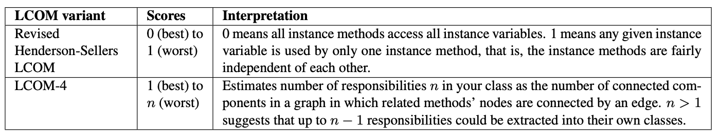
Figure 11.7: The “recommended” lack of cohesion of methods (LCOM) score depends heavily on which LCOM variant is
used. The table shows two of the most widely-used variants.